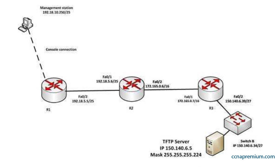
You have established a console session with R1 and you are attempting to download an IOS image from the TFTP server in the diagram below.
However, you are unable to make the connection to 150.140.6.5. What is the problem?
A. The IP address of the management station is incorrect
B. The interfaces between R1and R2 are not in the same subnet
C. The IP address of Switch B is incorrect
D. The IP address of the TFTP server is incorrect
Correct Answers: D
Explanation:
The IP address of the TFTP server is incorrect. The TFTP server, Switch B and the Fa0/2 interface on R3 should all be in the same subnet. With a 27-bit mask (255.255.255.224) against the 150.140.0.0 classful network the resulting subnets are:
150.140.0.0
150.140.0.32
150.140.0.64
and so on, incrementing in intervals of 32 in the last octet until it reaches the 150.140.6.0 subnet. 150.140.6.0
150.140.6.32
150.140.6.64
At this point, we can see that Switch B and the router interface are in the 150.140.6.32 subnet, while the TFTP server is in the 150.140.6.0 subnet. The IP address of the TFTP server needs to be in the 150.140.6.33-150.140.6.62 range, while avoiding the addresses already used on R1 and the switch.
The IP address of the management station does not appear to be in any of the networks listed in the diagram, but that doesn’t matter since the connection to the router is through the console cable which does not require a correct IP address.
The Fa0/2 and Fa0/1 interfaces on R1 and R2 are in the same subnet. Using a 25-bit mask against the 192.18.5.0/24 classful network yields the following subnets:
192.18.5.0
192.168.5.128
Both router interfaces in question are in the 192.18.5.0 subnet.
As we have already determined, the IP address of Switch B is correct. Even if it were incorrect or missing altogether, it would have no impact on connecting to the TFTP server. Switches merely switch frames based on MAC addresses and only need an IP address for management purposes.
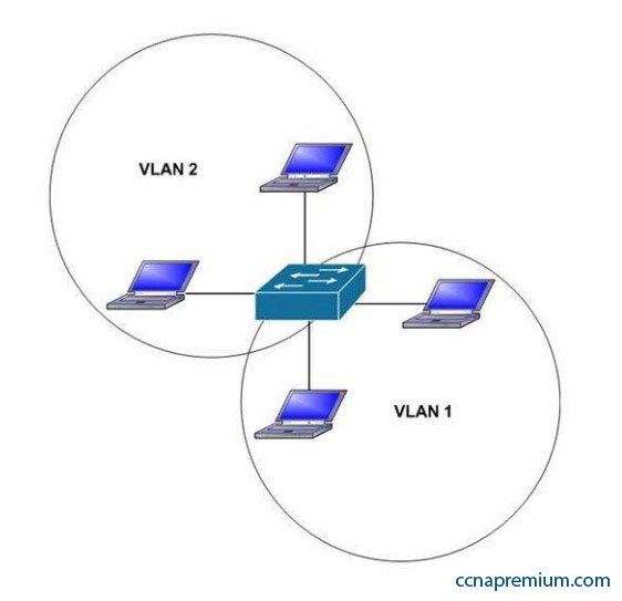
Which of the following statements are true with regard to the network shown in the exhibit?
A. there is one broadcast domain and one collision domain
B. there is one broadcast domain and four collision domains
C. there are two broadcast domains and two collision domains
D. there are two broadcast domains and four collision domains
E. the hosts in VLAN1 could use IP addresses 192.168.5.4/24 and 192.168.5.5/24 and the hosts in VLAN2 could use IP addresses 192.168.6.1/24 and 192.168.6.2/24
F. the hosts in VLAN2 could use IP addresses 192.168.5.5/24 and 192.168.6.5/24
Correct Answers: D, E
Explanation:
There are two broadcast domains and four collision domains in the network shown in exhibit. A Virtual LAN (VLAN) is a group of networking devices in the same broadcast domain. A broadcast domain is a group of devices such that when one device in the group sends a broadcast, all the other devices in the group will receive that broadcast. Because there are two VLANs shown in the exhibit, VLAN1 and VLAN2, there are two broadcast domains. A switch will not forward broadcast frames between VLANs.
A collision domain is a domain where two or more devices in the domain could cause a collision by sending frames at the same time. Each switch port is a separate collision domain. Because there are four switch ports in the exhibit, there are four collision domains.
The hosts in VLAN1 could use IP addresses 192.168.5.4/24 and 192.168.5.5/24 and the hosts in VLAN2 could use IP addresses 192.168.6.1/24 and 192.168.6.2/24. Hosts in different VLANs must have IP addresses that are in different subnets.
The other options that offer IP address plans are incorrect because they either place hosts from different VLANs in the same subnet, or place hosts in the same VLAN in different subnets.
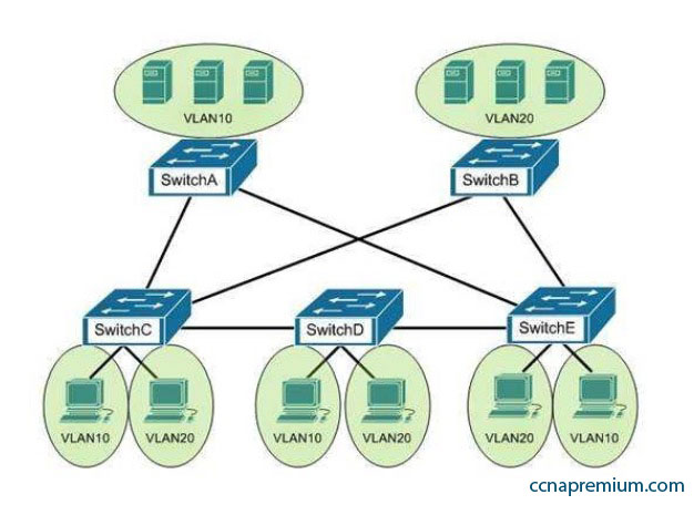
You are the switch administrator for InterConn. The network is physically wired as shown in the diagram. You are planning the configuration of STP. The majority of network traffic runs between the hosts and servers within each VLAN.
You would like to designate the root bridges for VLANS 10 and 20. Which switches should you designate as the root bridges?
A. Switch A for VLAN 10 and Switch E for VLAN 20
B. Switch A for VLAN 10 and Switch C for VLAN 20
C. Switch A for VLAN 10 and Switch B for VLAN 20
D. Switch D for VLAN 10 and Switch B for VLAN 20
E. Switch E for VLAN 10 and Switch A for VLAN 20
F. Switch B for VLAN 10 and Switch E for VLAN 20
Correct Answers: C
Explanation:
You should designate Switch A for VLAN 10 and Switch B for VLAN 20. The STP root bridge for a particular VLAN should be placed as close as possible to the center of the VLAN. If the majority of network traffic is between the hosts and servers within each VLAN, and the servers are grouped into a server farm, then the switch that all hosts will be sending their data to is the ideal choice for the STP root. Cisco’s default implementation of STP is called Per-VLAN Spanning Tree (or PVST), which allows individual tuning of the spanning tree within each VLAN. Switch A can be configured as the root bridge for VLAN 10, and Switch B can be configured as the root bridge for VLAN 20, resulting in optimized traffic flow for both.
None of the other switches is in the traffic flow of all data headed towards the VLAN 20 or VLAN 10 server farms, so they would not be good choices for the root bridge for either VLAN. Care should be taken when adding any switch to the network. The addition of an older, slower switch could cause inefficient data paths if the old switch should become the root bridge.
In the network exhibit, the routers are running OSPF and are set to the default configurations.
What would be the effect of configuring a loopback interface on Router A with an address of 192.168.1.50/24?
A. Router B would become the DR
B. Router A would become the DR
C. Router C would become the DR
D. Router A would become the BDR
Correct Answers: B
Explanation:
Configuring a loopback interface on RouterA with an address of 192.168.1.50/24 would cause Router A to become the designated router (DR). The designated router (DR) is determined by the router with the highest interface priority number. If the priority numbers are tied, then the router with the highest router ID (RID) becomes the DR.
The default priority number is 1, and can be configured as high as 255. Changing the priority to 0 would make the router ineligible to become the DR or the backup designated router (BDR). The ip ospf priority # command is used to manually configure a priority on a specific interface.
Router IDs are determined first by the highest loopback IP address, followed by the highest IP address on an active physical interface. Thus, in the case of a priority tie, the router with the highest loopback IP address will have the highest RID, and will become the DR for the network segment.
The current Router ID for a router can be determined by executing the show ip interface brief command. In the sample output of the show ip interface brief command below, the RID will be 10.108.200.5.
Router# show ip interface brief
Interface IP-Address OK? Method Status Protocol Ethernet0 10.108.00.5 YES NVRAM up up
Ethernet1 unassigned YES unset administratively down down Loopback0 10.108.200.5 YES NVRAM up up
Serial0 10.108.100.5 YES NVRAM up up Serial1 10.108.40.5 YES NVRAM up up Serial2 10.108.100.5 YES manual up up
Serial3 unassigned YES unset administratively down down
Neither Router B nor C will be the DR because the IP addresses on their physical interfaces are lower than 192.168.1.50/24. Router A will not be the backup designated router. Since it is the DR, it cannot also be the BDR.
Router C will not be the BDR because its IP address is lower than that of Router B. Router B will be the BDR.
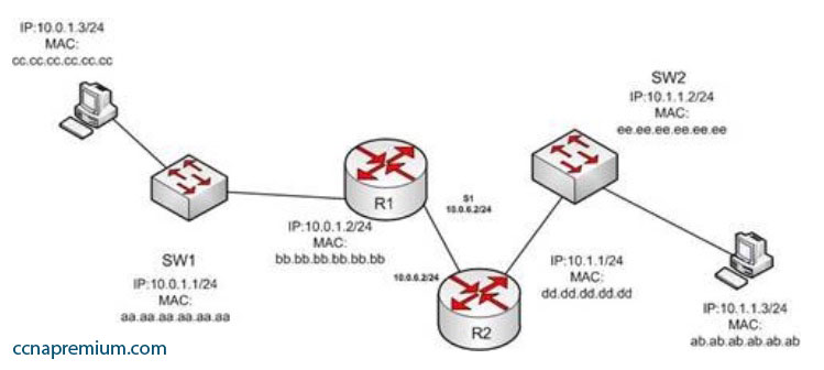
In the diagram below, if the workstation at 10.0.1.3 sends a packet to the workstation at 10.1.1.3, what will be the source physical address when the packet arrives at 10.1.1.3?
A. ab.ab.ab.ab.ab.ab
B. ee.ee.ee.ee.ee.ee
C. dd.dd.dd.dd.dd.dd
D. cc.cc.cc.cc.cc.cc
E. aa.aa.aa.aa.aa.aa
F. bb.bb.bb.bb.bb.bb
Correct Answers: C
Explanation:
The source physical address of the packet when it arrives at 10.1.1.3 will be that of the interface on the R2 router, dd.dd.dd.dd.dd.dd . Each router will change the MAC address field to the MAC address of its sending interface as it sends the packet and will leave the IP address field unchanged. The switches will change neither field, but will simply use the MAC address field to determine the forwarding path and switch the frame to the port where the MAC address is located. The R2 router is the last device that will make a change to the MAC address field.
The source (10.0.1.3) and destination (10.1.1.3) IP address fields will stay the same at each device. The MAC address field changes when R1 sends the frame to R2 and when R2 send the frame to the workstation at 10.1.1.3.
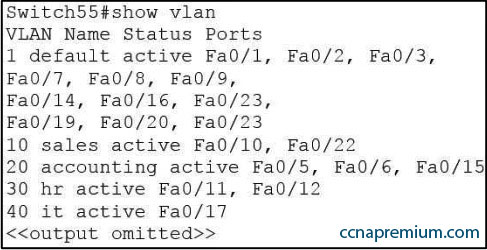
You are connecting a new computer to Switch55. The new computer should be placed in the Accounting VLAN. You execute the show vlan command and get the following output:
Examine the additional network diagram.
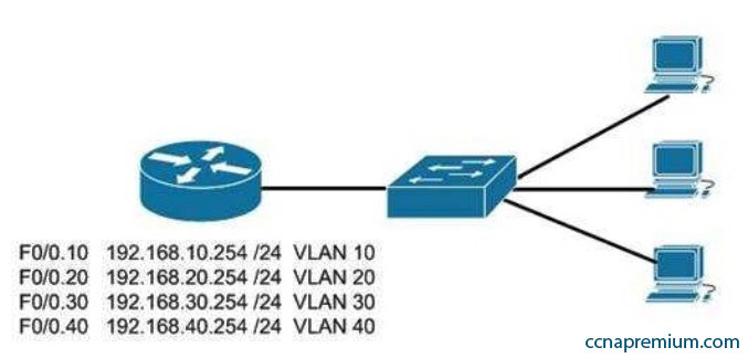
What action should you take to place the new computer in the Accounting VLAN and allow for inter-VLAN routing?
A. Connect the new computer to Fa0/1
B. Connect the new computer to Fa0/14
C. Connect the new computer to Fa0/5
D. Configure a dynamic routing protocol on the router interface
Correct Answers: C
Explanation:
Switchport Fa0/5 can be used to place the computer in the Accounting VLAN.
The diagram indicates that a router has been configured as a “router-on-a-stick” to perform inter-VLAN routing between VLANs 10, 20, 30 and 40. The show vlan output indicates that interfaces Fa0/5, Fa0/15, and Fa0/6 have been assigned to VLAN 20, the Accounting VLAN:
20 accounting active Fa0/5, Fa0/6, Fa0/15
Switchports Fa0/1 and Fa0/14 are both in the default VLAN, as indicated by the portion of the output describing the switch ports that are unassigned and therefore still residing in the default VLAN:
It is not necessary to configure a dynamic routing protocol on the router. Since the router is directly connected to all four subinterfaces and their associated networks, the networks will automatically be in the router’s routing table, making inter-VLAN routing possible.
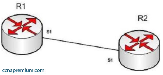
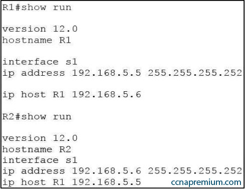
R1 and R2 are connected as shown in the diagram and are configured as shown in output in the partial output of the show run command.
The command “ping R2” fails when executed from R1. What command(s) would allow R1 to ping R2 by name?
A.
R1(config)#int S1
R1(config-if)#no ip address 192.168.5.5
R1(config-if)#ip address 192.168.5.9 255.255.255.252
B.
R1(config)#no ip host R1
R1(config)#ip host R2 192.168.5.6 255.255.255.252
C.
R1(config)#no hostname R2
R1(config)# hostname R1
D.
R2(config)#int S1
R1(config-if)#no ip address 192.168.5.5
R1(config-if)# ip address 192.168.5.9 255.255.255.0
Correct Answers: B
Explanation:
Both routers have been configured with the ip host command. This command creates a name to IP address mapping, thereby enabling the pinging of the device by address. On R1, the mapping is incorrect and needs to be corrected. Currently it is configured as ip host R1 192.168.5.6. It is currently mapping its own name to the IP address of R2.
To fix the problem, you should remove the incorrect IP address mapping and create the correct mapping for R2, as follows:
R1(config)#no ip host R1
R1(config)# ip host R2 192.168.5.6 255.255.255.252
Once this is done, the ping on R2 will succeed.
The IP address of the S1 interface on R1 does not need to be changed to 192.168.5.9 /30. In fact, if that is done the S1 interface on R1 and the S1 interface in R2 will no longer be in the same network. With a 30-bit mask configured, the network they are currently in extends from 192.168.5.4 – 192.168.5.7. They are currently set to the two usable addresses in that network, 192.168.5.5 and 192.168.5.6.
The hostnames of the two routers do need to be set correctly using the hostname command for the ping to function, but they are correct now and do not need to be changed.
The subnet mask of the S1 interface on R2 does not need to be changed to 255.255.255.0. The mask needs to match that of R1, which is 255.255.255.252
/div>
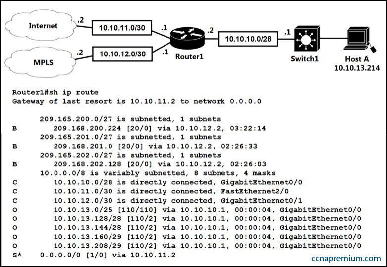
Refer to the exhibit. Which prefix does Router 1 use for traffic to Host A?
A. 10.10.10.0/28
B. 10.10.13.0/25
C. 10.10.13.144/28
D. 10.10.13.208/29
Correct Answers: D
Explanation:
The prefix with “longest prefix” will be matched first, in this case is “/29”.
Because each entry in a forwarding table may specify a sub-network, one destination address may match more than one forwarding table entry. The most specific of the matching table entries — the one with the longest subnet mask — is called the longest prefix match. It is called this because it is also the entry where the largest number of leading address bits of the destination address match those in the table entry.
Reference: https://en.wikipedia.org/wiki/Longest_prefix_match
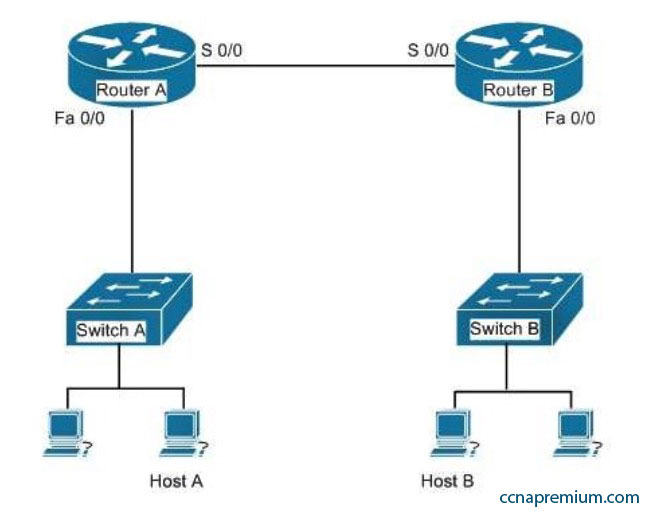
You have just finished configuring a small test network as part of his training. The network is configured as shown in the diagram below:
When testing the configuration, you find that Host A in the diagram cannot ping Host B.
Which of the following pairs of connections are required to be in the same subnet for Host A to be able to ping Host B? (Choose all that apply.)
A. The IP address of Host A and the IP address of the Fa0/0 interface of Router A
B. The IP address of the Fa0/0 interface of Router A and the IP address of the Fa0/0 interface of Router B
C. The IP address of Host A and the IP address of the Fa0/0 interface of Router B
D. The IP address of Host A and the IP address of Switch A
E. The IP address of the S 0/0 interface of Router A and the IP address of the S 0/0 interface of Router B
F. The IP address of Host A and the IP address of Host B
G. The IP address of Host B and the IP address of the Fa0/0 interface of Router B
Correct Answers: A, E, G
Explanation:
The following pairs of connections are required to be in the same subnet:
– the IP address of Host A and the IP address of the Fa0/0 interface of Router A
– the IP address of the S 0/0 interface of Router A and the IP address of the S 0/0 interface of Router B the IP address of Host B and the IP address of the Fa0/0 interface of Router B
When troubleshooting a correctly labeled network diagram for IP addressing problems, one must start on one end and trace each link in one direction, ensuring at each step that the interfaces are in the same subnet. A switch simply passes the packet to the router; therefore, the IP address of the switch is not important. It performs its job even if it has no IP address.
Moving from Host A to Host B, however, the following links must be in the same subnet: The IP address of Host A and the IP address of the Fa0/0 interface of Router A
The IP address of the S0/0 interface of Router A and the IP address of the S0/0 interface of Router B The IP address of Host B and the IP address of the Fa0/0 interface of Router B
Neither of the switch addresses is important to the process.
If all other routing issues are correct, it is also not required for Host A and Host B to be in the same subnet.
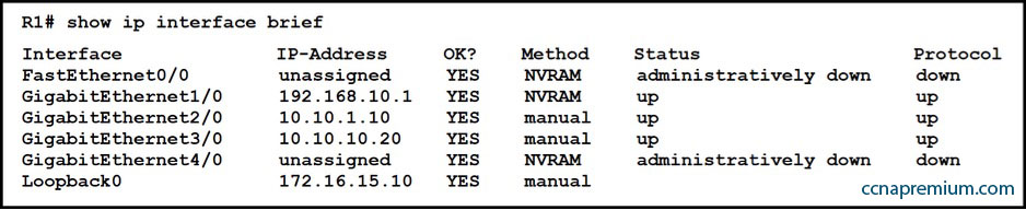
Refer to the exhibit. What does router R1 use as its OSPF router-ID?
A. 10.10.1.10
B. 10.10.10.20
C. 172.16.15.10
D. 192.168.0.1
Correct Answers: C
Explanation:
OSPF uses the following criteria to select the router ID:
1. Manual configuration of the router ID (via the “router-id x.x.x.x” command under OSPF router configuration mode).
2. Highest IP address on a loopback interface.
3. Highest IP address on a non-loopback and active (no shutdown) interface.