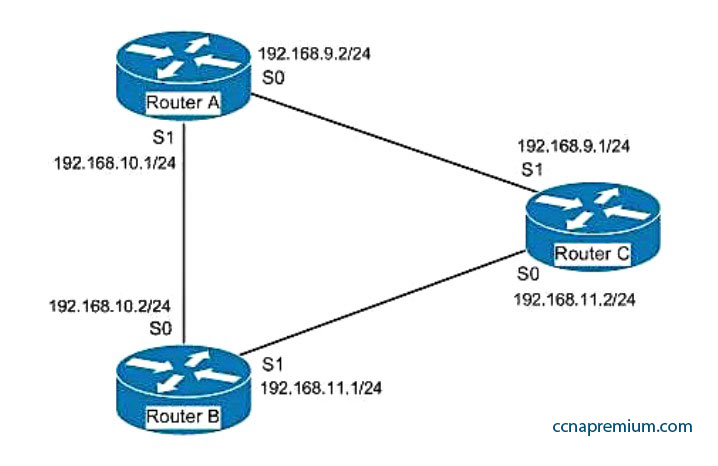
You have three EIGRP routers that are connected as shown in the diagram below.
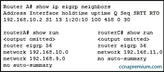
Router A and Router C do not seem to be exchanging information. You execute commands on all three routers, and receive as output the information shown below:
What needs to be done to make Routers A and C start exchanging information?
A. Execute the auto-summary command on Router A
B. Correct the IP address on the S1 interface of Router C
C. Recreate the EIGRP configuration on Router C as EIGRP 55
D. Execute the network 192.168.9.0 command under EIGRP 56 on Router C
Correct Answers: D
Explanation:
Router C is not displayed in the neighbor table of Router A, which indicates that Router C and Router A are not forming a neighbor relationship or exchanging information. This is because Router C does not have EIGRP configured for its S1 interface. You can see this is missing from its configuration in the output of the show run command for RouterC. To solve the issue, you should execute the network 192.168.9.0 command under the EIGRP 56 configuration on Router C. Then Router C will start sending hellos on that interface and the two routers will become neighbors.
The show ip eigrp neighbors command displays the following information for each EIGRP neighbor. In parentheses is the value of each found in the output of router A for Router B:
IP address (192.168.10.2)
Local interface (S1)
Retransmit interval (13)
Queue count (100)
There is no need to execute the auto-summary command on Router A. It will not affect the establishment of a neighbor relationship between Routers A and C.
There is no need to correct the IP address on the S1 interface of Router C. The address 192.168.9.1 is correctly located in the same subnet as the address on S0 of Router A.
Finally, changing the EIGRP configuration on Router C to EIGRP 55 will not help. Router C will not start sending hellos on its S1 interface until EIGRP is enabled on the S1 interface. Until then, the Routers A and C will not form a neighbor relationship and will not share information.
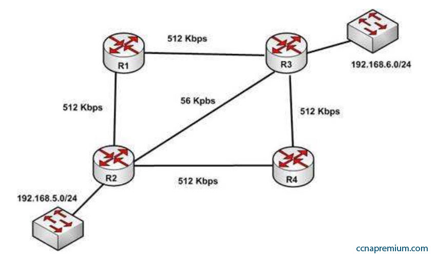
With respect to the network shown below, which of the following statements are true when R2 sends a packet to the 192.168.6.0/24 network?
A. If RIPv1 is in use, the path taken will be R2 – R4 – R3
B. If both RIPv2 and EIGRP are in use, the EIGRP route will be placed in the routing table
C. If EIGRP is in use, the only path taken will be R2 – R4 – R3
D. If RIPv2 is in use, the path taken will be R2 – R3
Correct Answers: B, D
Explanation:
If both RIPv2 and EIGRP are in use, the EIGRP route will be placed in the routing table. If RIPv2 is in use, the path taken will be R2 – R3.
EIGRP has a default administrative distance (AD) of 90, while RIPv2 has a default administrative distance (AD) of 120. The route learned by the routing protocol with the lowest AD will be placed in the routing table.
If you wanted to force R2 to use the RIPv2 route instead of the EIGRP route, this could be accomplished by changing the administrative distance of RIPv2 to a value less than 90, such as 80. The commands that would accomplish this are:
If either of the versions of RIP is in use, hop count is used to determine the route. The path with the least number of hops is R2 – R3. If RIPv1 is in use, the path taken would be R2 – R3, not R2 – R4 – R3, because R2 – R3 has a lower hop count.
If EIGRP is in use, the path R2 – R4 – R3 will not be the only path taken. EIGRP load-balances two equal cost paths when they exist, and R2 – R4 – R3 and R2 – R1 – R3 are of equal cost so would both be used.
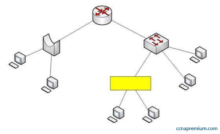
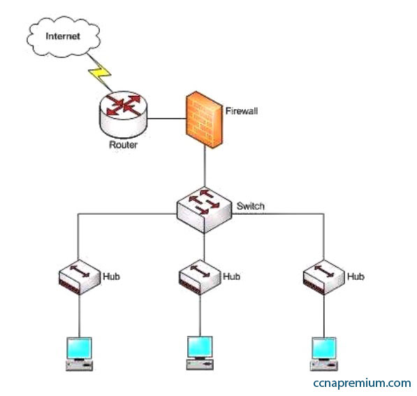
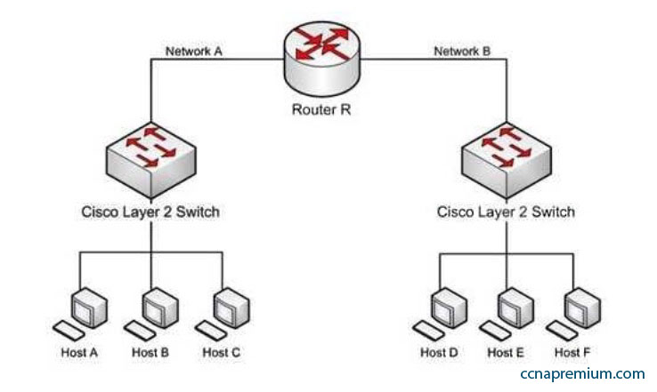
Assume that all ports on Layer 2 devices are in the same Virtual LAN (VLAN). View the given network topology.
Which network device should be placed at the highlighted box to produce a total of two broadcast domains and seven collision domains in the network?
A. Hub
B. Bridge
C. Switch
D. Router
Correct Answers: A
Explanation:
A hub should be placed at the highlighted box to produce a total of two broadcast domains and seven collision domains in the network. Network devices segment collision domains and broadcast domains in the following manner:
– Hub: A Layer 1 device with all ports in same collision domain and broadcast domain.
– Bridge/Switch: Layer 2 devices on which all ports are in different collision domains, but in the same broadcast domain (assuming that all ports are in the same VLAN or no VLAN is configured).
– Routers: A Layer 3 device on which every port is a separate collision as well as broadcast domain.
The bridge shown in the graphic has three ports populated by active links, resulting in three collision domains. The switch shown in the exhibit has four ports populated with the links, resulting in four collision domains. Together these two devices create seven collision domains.
Because the scenario requires that there be no more than seven collision domains, the device in the highlighted box must not create any further collision domains. A hub is a device that has all its ports in the same collision domain and will not create any further collision domains in the topology.
A bridge or switch cannot be the correct option because these will also add collision domains.
In the exhibit, the router has two ports with active links, which will result into two broadcast domains. Because the scenario states there are no more than two broadcast domains, the device in the highlighted box must not be a router. Routers are used to segment broadcast domains.
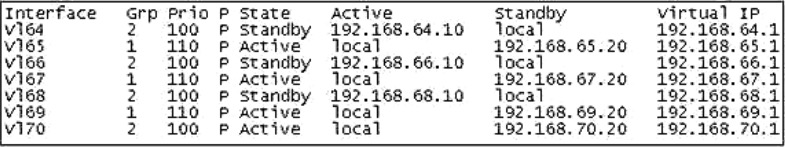
What command would provide the output displayed in the exhibit?
A. switch# show hsrp
B. switch# show standby
C. switch# show interface vlan
D. switch# show standby brief
Correct Answers: D
Explanation:
The command show standby brief displays the output in the exhibit. It is used to display a summary of the HSRP groups of which the switch is a member. The summary information it provides includes the group number, priority, state, active device address, standby address, and group address. In the exhibit, the interface VLAN 64 is a member of HSRP group 2. Its priority in the group is 100 and it is currently the standby switch. Since preemption is configured (as indicated by the P following the priority), we know that the priority of this switch must be lower than the priority of the active device. The active device has an IP address of 192.168.64.10 and the group IP address is 192.168.64.1.
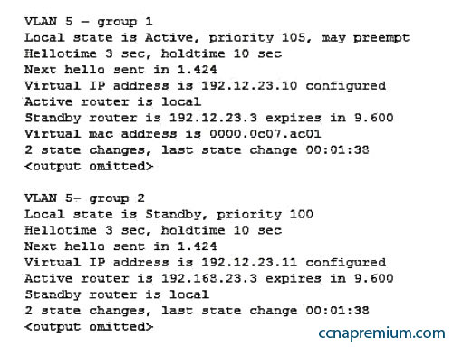
The command show standby can be used to display detailed information about HSRP groups of which a switch is a member. It does not provide the quick summary display of the exhibit. This command displays information about HSRP on all configured interfaces and for all HSRP groups. It also displays hello timer information and the expiration timer for the standby switch. The command syntax is show standby [type number [group]].
Below is an example of this command’s output:
In the above output, Router A is load-sharing traffic for VLAN 5. It is active for group 1 and standby for group 2. The router at address 192.168.23.3 is active for group 2 and standby for group 1. This allows traffic to be sent to both routers while still allowing for redundancy. Router A was also configured with the standby 1 preempt command (results seen in line 1), which allows it to resume its role as active for group 1 if it comes back up from an outage.
The command show interface vlan is not a complete command. A VLAN number must follow the command. When provided with a VLAN number, the output would display the status of the SVI, but no HSRP information.
The command show hsrp is not a valid command due to incorrect syntax.
Which device in the given network diagram has as its primary responsibility the regulation of network traffic flow based on different trust levels for different computer networks?
A. the router
B. the switch
C. the hub(s)
D. the firewall
Correct Answers: D
Explanation:
The firewall has as its primary responsibility the regulation of network traffic flow based on different trust levels for different computers or networks. In the network diagram shown in the exhibit, a firewall protects the network from unauthorized access attempts. A firewall can be implemented in hardware or software. Firewalls permit, deny, or filter data packets coming into and going out of the network. This helps prevent unauthorized access attempts from outside the network.
The primary function of a router is to perform routing between two subnets or between dissimilar network technologies. Routers can provide limited firewall functionality, but a firewall is a dedicated hardware or software solution with the primary responsibility of securing the network. A router does not have as its primary responsibility the regulation of network traffic flow based on different trust levels.
Switches work at Layer 2 in the Open System Interconnection (OSI) model and perform the function of separating collision domains. A switch does not have as its primary responsibility the regulation of network traffic flow based on different trust levels.
A hub is a device that provides a common connection point for network devices. The primary responsibility of a hub is not to regulate network traffic flow based on different trust levels.
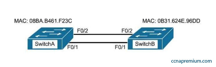
A. SwitchA
B. SwitchB
C. SwitchC
D. The root bridge cannot be determined from the given information.
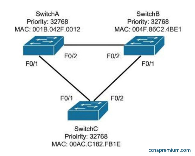
Correct Answers: A
Explanation:
SwitchA will become the root bridge. The bridge ID, also known as the switch ID, is used to elect the root bridge in a redundant network topology. The bridge ID has two components:
– Switch’s priority number: Configured as 32768 on Cisco switches by default
– Switch’s Media Access Control (MAC) address: The burnt-in hardware address of the network interface card
The switch with the lowest bridge ID is selected as the root bridge. If the same priority number is configured on two or more switches in the network, the switch with the lowest MAC address will become the root. Bridge Protocol Data Units (BPDUs) communicate the details of the switch with the lowest bridge ID in the network. The election process for the root bridge takes place every time there is a topology change in the network. A topology change may occur due to the failure of a root bridge or the addition of a new switch in the network. The root bridge originates BPDUs every two seconds, which are propagated by other switches throughout the network. BPDUs are used as keepalives between switches, and if a switch stops receiving BPDUs from a neighboring switch for ten intervals (20 seconds), it will assume a designated role for the network segment.
Neither SwitchB nor SwitchC will become the root bridge. Although both have an equal priority value to SwitchA (32768), the MAC addresses of SwitchB and SwitchC are higher than that of SwitchA.
The root bridge can be determined with the information given. If the diagram did not indicate MAC addresses, then the root bridge would not be able to be determined, since the priorities are equal.
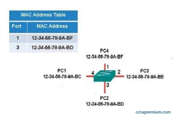
The following exhibit displays the MAC address table of a switch in your network, along with the location of each device connected to the switch:
Which of the following frames will be flooded to all ports after it is received by the switch?
A. source MAC: 12-34-56-78-9A-BD, destination MAC: 12-34-56-78-9A-BF
B. source MAC: 12-34-56-78-9A-BF, destination MAC: 12-34-56-78-9A-BD
C. source MAC: 12-34-56-78-9A-BF, destination MAC: 12-34-56-78-9A-BC
D. source MAC: 12-34-56-78-9A-BC, destination MAC: 12-34-56-78-9A-BF
Correct Answers: C
Explanation:
The frame with a source MAC of 12-34-56-78-9A-BF and a destination MAC of 12-34-56-78-9A-BC would be sent to all ports because the destination MAC address is not already in the MAC address table.
The frame with a source MAC of 12-34-56-78-9A-BD and a destination MAC of 12-34-56-78-9A-BF would not be sent to all ports because the destination MAC address is in the MAC address table.
The frame with a source MAC of 12-34-56-78-9A-BF and a destination MAC of 12-34-56-78-9A-BD would not be sent to all ports because the destination MAC address is in the MAC address table.
The frame with a source MAC of 12-34-56-78-9A-BC and a destination MAC of 12-34-56-78-9A-BF would not be sent to all ports because the destination MAC address is in the MAC address table.
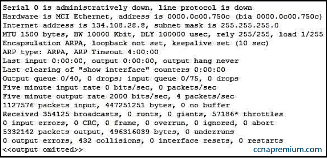
Refer to the partial output of the show interfaces command:
What does the Serial 0 is administratively down, line protocol is down line indicate with certainty?
A. There is no problem with the physical connectivity.
B. There is a configuration problem in the local or remote router.
C. There is a problem at the telephone company’s end.
D. The shutdown interface command is present in the router configuration.
Correct Answers: D
Explanation:
The Serial 0 is administratively down, line protocol is down line in the output of the show interfaces command indicates the following:
The shutdown interface command is present in the router configuration. This indicates that the administrator might have manually shut down the interface by issuing the shutdown command.
A duplicate Internet Protocol (IP) address might be in use.
This line does not show that there is no problem with the physical connectivity. Since the interface is administratively shut down, there is no way of determining the operational status of the physical layer.
The Serial 0 is administratively down, line protocol is down line does not indicate a configuration problem in the local or remote router. A problem in the configuration of local or remote router would be indicated by the Serial 0 is up, line protocol is down message.
This line does not show that there is a problem at the telephone company’s end. Since the interface is administratively shut down, there is no way of determining the operational status of the physical layer or protocol layer on the other end of the line.
Which switch port(s) will be in a forwarding state? (Choose two.)
A. SwitchA – Fa0/1 and Fa0/2
B. SwitchA – Fa0/1
C. SwitchA – Fa0/2
D. SwitchB – Fa0/1
E. SwitchB – Fa0/2
Correct Answers: A, D
Explanation:
Both switch ports on Switch A and Fa0/1 on Switch B will be in a forwarding state. Switch A will become the STP root bridge due to its lower MAC address. All ports on the root bridge will become designated ports in a forwarding state. Switch B has redundant connectivity to the root bridge, and must block one of its interfaces to prevent a switching loop. Both interfaces are the same speed (FastEthernet), and thus their cost to the root is the same. Finally, the interface with the lowest number will become the forwarding port. F0/1 has a lower port number than F0/2, so F0/1 becomes a forwarding port, and F0/2 becomes a blocking port.
In this scenario there are only two switches in the diagram. However, if there were more switches and Switch A were not the root bridge, the result would be the same with regard to the ports between Swicth A and B. Whenever there are redundant links between switches, one of the four ports involved will be set to a blocking (or in the case of RSTP, discarding) mode. The logic will still be the same, since the cost to get to the root bridge will still be equal if the port speeds are equal.
Without STP (which can be disabled) operating on switches with redundant links, such as those in the figure, loops can and almost surely will occur. For example, if a host connected to SwitchA were to send an ARP request for the MAC address of a host connected to SwitchB, the request could loop and cause a broadcast storm, slowing performance dramatically. This would probably occur when any host connected to either switch sends a broadcast frame, such as a DHCP request.
Rapid Spanning Tree Protocol (RSTP) uses the term discarding for a switch port that is not forwarding frames.
Refer to the network diagram in the exhibit. Host A is configured with an incorrect default gateway. All other computers and the Router are known to be configured correctly.
Which of the following statements is TRUE?
A. Host C on Network A cannot communicate with Host A on Network A.
B. Host A on Network A can communicate with all other hosts on Network A.
C. Host A on Network A can communicate with Router R.
D. Host C on Network A cannot communicate with Router R.
E. Host D on Network B cannot communicate with Host B on Network A.
Correct Answers: B, C
Explanation:
Host A on Network A can communicate with all other hosts on Network A and with Router R. To communicate with local hosts and the interface of Router R (which are all in the same subnet) only a correct IP address is reqired. If the default gateway of Host A is incorrect, then it will not be able to communicate with any host on the other side of the router, which includes Network B in the diagram. Packets from hosts on Network B will reach Host A on Network A without any problem, because they possess the correct address of the default gateway or router, but Host A will send the packet to a dead end because Host A has an incorrect default gateway. On the other hand, Host A does not require a default gateway to communicate with other hosts on same network.
Host C on Network A WILL be able to communicate with Host A on Network A , even though Host A has an incorrect default gateway because Host A and C are in the same subnet, which requires no use of the of the gateway or router..
Host C on Network A WILL be able to communicate with Router R because Host C has the correct default gateway address which is the address of Router R. Host D on Network B WILL be able to communicate with Host B on Network A because both hosts have a correct default gateway address.