CISCO CCNA 200-301 Q37

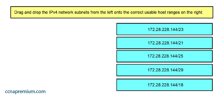
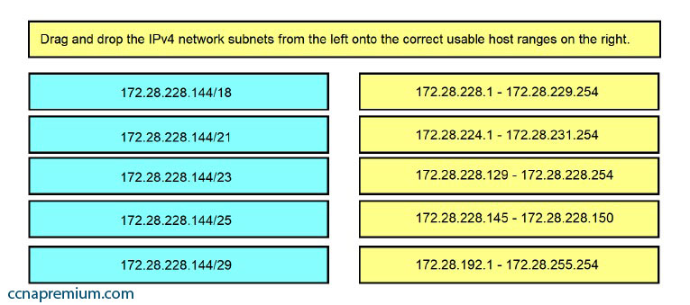
Drag and drop the IPv4 network subnets from the left onto the correct usable host ranges on the right. Select and Place:

Correct Answers:

CISCO CCNA 200-301 Q36

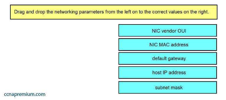
Refer to the exhibit. Drag and drop the networking parameters from the left on to the correct values on the right.
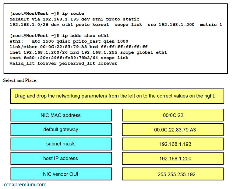
Correct Answers:

CISCO CCNA 200-301 Q33

You are a network administrator for your organization. Your organization has two Virtual LANs (VLANs) named Marketing and Production. All switches in the network have both VLANs configured on them. Switches A, C, F, and G have user machines connected for both VLANs, while switches B, D, and E have user machines connected for the Production VLAN only.


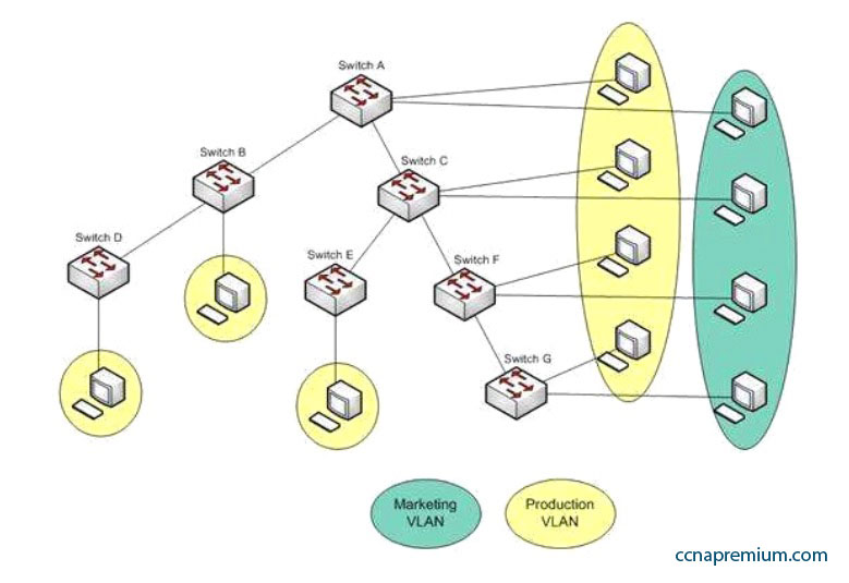
To reduce broadcast traffic on the network, you want to ensure that broadcasts from the Marketing VLAN are flooded only to those switches that have Marketing VLAN users. Which Cisco switch feature should you use to achieve the objective?

A. PVST
B. RSTP
C. VTP Pruning
D. Dynamic VLANs

Correct Answers: C

Explanation:
The VLAN Trunking Protocol (VTP) pruning feature of Cisco VTP allows switches to dynamically delete or add VLANs to a trunk. It restricts unnecessary traffic, such as broadcasts, to only those switches that have user machines connected for a particular VLAN. It is not required to flood a frame to a neighboring switch if that switch does not have any active ports in the source VLAN. A trunk can also be manually configured with its allowed VLANs, as an alternative to VTP pruning.

All other options are incorrect because none of these features can be used to achieve the objective in this scenario.

The Per-VLAN Spanning Tree (PVST) feature allows a separate instance of Spanning Tree Protocol (STP) per VLAN. Each VLAN will have its own root switch and, within each VLAN, STP will run and remove loops for that particular VLAN.

Rapid Spanning Tree Protocol (RSTP) is an Institute of Electrical and Electronics Engineers (IEEE) standard. It reduces high convergence time that was previously required in STP implementations. It is interoperable with STP (802.1d).

With dynamic VLANs, the switch automatically assigns a switch port to a VLAN using information from the user machine, such as its Media Access Control (MAC) address or IP address. The switch then verifies information with a VLAN Membership Policy Server (VMPS) that contains a mapping of user machine information to VLANs.

CISCO CCNA 200-301 Q32

The workstation at 10.0.1.3 sends a packet to the workstation at 10.1.1.3.


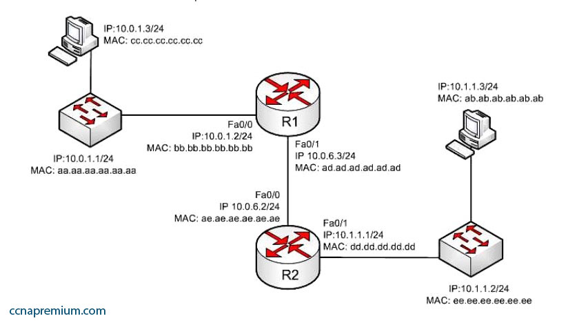
When the packet leaves the R2 router, what addresses will be located in the header? (Choose two.)

A. Source MAC bb.bb.bb.bb.bb.bb Dest MAC ab.ab.ab.ab.ab.ab
B. Source MAC dd.dd.dd.dd.dd.dd Dest MAC ab.ab.ab.ab.ab.ab
C. Source MAC ee.ee.ee.ee.ee.ee Dest MAC ab.ab.ab.ab.ab.ab
D. Source IP 10.0.1.3 Dest IP 10.1.1.3
E. Source IP 10.0.1.1 Dest IP 10.1.1.2
F. Source IP 10.0.1.2 Dest IP 10.1.1.3
G. Source IP 10.0.1.1 Dest IP 10.1.1.3

Correct Answers: B, D

Explanation:
When the packet leaves the R2 router, the addresses that will be located in the header are:

Source MAC dd.dd.dd.dd.dd.dd Dest MAC ab.ab.ab.ab.ab.ab Source IP 10.0.1.3 Dest IP 10.1.1.3

If we executed the ipconfig/all command on the computer located at 10.1.1.3/24, it would look somewhat like what is shown below. The router interface (10.1.1.1/24) would use an ARP broadcast to determine the MAC address associated with the IP address 10.1.1.3/24 and it would be returned as ab.ab.ab.ab.ab. The router interface would then encapsulate the packet in a frame addressed to ab.ab.ab.ab.ab.

The source and destination IP address never change as the packet is routed across the network. The MAC address will change each time a router sends the packet to the next router or to the ultimate destination. The switches do not change either set of addresses in the header; they just switch the frame to the correct switch port according to the MAC address table. Therefore, when the packet leaves R2, the source MAC address will be that of R2, and the destination will be that of the workstation at 10.1.1.3. The IP addresses will be those of the two workstations, 10.0.1.3 and 10.1.1.3.

When the workstation at 10.0.1.3 starts the process, it will first determine that the destination address is in another subnet, and will send the packet to its default gateway at 10.0.1.2. It will perform an ARP broadcast for the MAC address that goes with 10.0.1.2, and R1 will respond with its MAC address, bb.bb.bb.bb.bb.bb.

After R2 determines the next-hop address to send to 10.0.1.3 by parsing the routing table, it will send the packet to R1 at 10.0.6.2. When R2 receives the packet, R2 will determine that the network 10.0.1.0/24 is directly connected and will perform an ARP broadcast for the MAC address that goes with 10.0.1.3. The workstation at 10.0.1.3 will respond with its MAC address, ab.ab.ab.ab.ab.ab.

CISCO CCNA 200-301 Q31

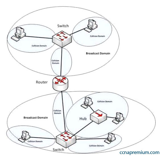
How many collision and broadcast domains are in the network shown below?


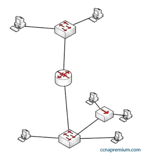
A. 4 collision domains and 3 broadcast domains
B. 7 collision domains and 2 broadcast domains
C. 8 collision domains and 1 broadcast domain
D. 6 collision domains and 2 broadcast domains

Correct Answers: B

Explanation:
There are 7 collision domains and 2 broadcast domains. They are labeled as shown below. Each router interface makes a broadcast domain and each switch interface creates a collision domain. The hub interfaces do neither.

CISCO CCNA 200-301 Q30

Your network is configured as shown in the following exhibit. When you trace traffic sourced from R3 destined for a LAN network off of R2 (not shown in the diagram), you see the traffic is being forwarded from R1 to ISP1 rather than to R2.


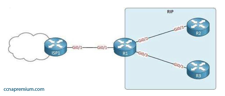
Which of the following issues could NOT be causing this behavior?

A. The network command has not been executed on the interface leading to the LAN off R2
B. A default route exists on R1 that leads to ISP1
C. RIPv2 has not been enabled on R2
D. The passive interface command has been issued on the Gi0/4 interface of R1

Correct Answers: D

Explanation:
This issue would NOT be caused by executing the passive interface command on the Gi0/4 interface of R1. This command prevents the advertisement of RIP routes on that interface. If that command had been issued, the traffic would not be forwarded to R1 because R3 would not know about the route to the LAN off of R2. This command would also prevent R3 from knowing about the default route to ISP1. Since the traffic is being routed to ISP1, this command must not have been executed.

All of the other options could potentially because traffic destined for R2 to be forwarded from R1 to ISP1, rather than to R2.

It is true that a default route exists on R1 that leads to ISP1. If this default route did not exist, the traffic destined for R2 would simply be dropped at R1 instead of being forwarded to ISP1.

If the network command has not been executed on the interface leading to the LAN off of R2, the network leading to the LAN off R2 would not advertised by R2.
That would make R1 unaware of this destination. In that case, R1 would use the default route to send traffic destined for R2 to ISP1. We know such a default route must exist, or the traffic would simply be dropped at R1.

If RIPv2 has not been enabled on R2, R2 would not be receiving or advertising any RIP routes. When the packets destined for the network off of R2 arrive at R1, R1 will have not have a route to that network. In that case R1 will forward the traffic to ISP1 using the default route.

CISCO CCNA 200-301 Q29

Examine the following diagram:


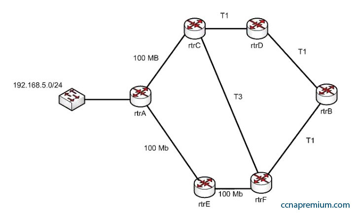
While troubleshooting an OSPF routing problem, you need to determine the cost for Router F to reach the 192.168.5.0 24 network via the best route. What will that cost be?

A. 2
B. 3
C. 7
D. 110

Correct Answers: A

Explanation:
The best route to the 192.168.5.0/24 network from the perspective of router F will have an OSPF assigned cost of 2. There are three possible loop-free paths to get from router F to the 192.168.5.0/24 network. The default OSPF costs for a 100 MB link, a T1 link, and a T3 link are 1, 64, and 2, respectively.

The three paths and the calculation of their costs are shown:

Router F to Router E to Router A: 1 + 1 = 2 Router F to Router C to Router A: 2 + 1 = 3
Router F to Router B to Router D to Router C to Router A: 64 + 64 + 64 + 1 = 193

Each OSPF route calculates the cost of its path to a network, and passes that value on to the next router, which will then add to it the cost to reach that neighbor. For example, the routing table of Router E would look like this for the route to 192.168.5.0/24:

O 192.168.5.0 [110/1] via

Router F would add its own cost to reach Router E to the cost of reaching 192.168.5.0/24, resulting in the following output:

O 192.168.5.0 [110/2] via
110 is the administrative distance of OSPF.

CISCO CCNA 200-301 Q28

Host A is configured for DHCP, but it is not receiving an IP address when it powers up. What is the most likely cause?


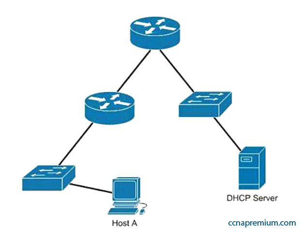
A. The DHCP server is on the wrong subnet.
B. Routers do not forward broadcast traffic.
C. The DHCP server is misconfigured.
D. Port security is enabled on the switch.

Correct Answers: B

Explanation:
Host A is not receiving a DHCP configuration because its initial DHCP Discover frame is a broadcast, and routers do not forward broadcast frames by default.

A DHCP client sends out a DHCP Discover packet when booting up, enveloped within an Ethernet broadcast frame. The broadcast frame will be flooded by switches, but filtered by routers. There must either be a DHCP server on the local subnet or a DHCP Relay Agent, which will forward the request from the local subnet to the DHCP server.

The DHCP server is not on the wrong subnet. A DHCP server can be centrally located and configured to support multiple remote subnets, as long as those subnets have DHCP Relay Agents configured to forward the DHCP Discover requests.

No information is provided on the DHCP server configuration. The router is the most obvious cause of the problem, so this option is incorrect.

Port security can be configured to restrict hosts based on the MAC address, but the scenario does not provide information on any port security configurations. The router is the most obvious cause of the problem as shown in the network exhibit.

CISCO CCNA 200-301 Q27

Your company’s network must make the most efficient use of the IP address space. In the following diagram, the circles define separate network segments. The requirements of each network segment are given in the diagram.


Users complain of connectivity issues. You need to discover the problems with the network configuration. What are the three problems with the network diagram? (Choose three.)

A. The 172.16.1.0/30 segment requires more user address space.
B. The 172.16.2.0/26 segment requires more user address space.
C. The 172.16.3.0/25 segment requires more user address space.
D. The 172.16.2.64/26 segment requires more user address space.
E. Interface fa0/2 has an IP address that belongs to the 172.16.2.64/26 segment.
F. Interface fa0/4 has an IP address that belongs to the 172.16.2.0/26 segment.
G. Interface fa0/3 has an IP address outside the 172.16.3.0/25 segment.

Correct Answers: A, F, G

Explanation:
The given exhibit has three problems:
– The 172.16.1.0/30 segment requires more user address space.
– Interface Fa0/4 has an IP address that belongs to the 172.16.2.0/26 segment. Interface –
– Fa0/3 has an IP address outside the 172.16.3.0/25 segment.

The 172.16.1.0/30 segment, as configured, will only support two hosts. This segment needs to support three hosts, the two servers, and the Fa0/1 interface. The number of hosts that a subnet is capable of supporting is a function of the number of host bits in the subnet mask. When that has been determined, the following formula can be used to determine the number of hosts yielded by the mask:
2n – 2 = X
(where n = the number of host bits in the mask and X = the number of hosts supported)

In this example with a 30-bit mask, 2 host bits are left in the mask. When that is plugged into the formula, it yields only two usable addresses. The -2 in the formula represents the two addresses in each subnet that cannot be assigned to hosts, the network ID and the broadcast address. Therefore, the segment should be configured with the 172.16.1.0/29 address range, which supports up to six hosts.

Interface fa0/4, as configured, has an IP address that belongs to the 172.16.2.0/26 segment. With a 26-bit mask and the chosen class B address, the following network IDs are created:

172.16.0.0
172.16.0.64
172.16.1.128
172.16.1.192
172.16.2.0
172.16.2.64
172.16.2.128
172.16.2.192
172.16.2.0
172.16.2.64
172.16.2.128
172.16.2.192
…and so on, incrementing each time by 64 in the last octet

The 172.16.2.0/26 segment is allocated host addresses in the 172.16.2.1 through 172.16.2.62 range (the last address, 172.16.2.63, is the broadcast address and cannot be assigned). Interface fa0/4 should be assigned an IP address in the 172.16.2.64/26 range, which includes host addresses in the 172.16.2.65 through 172.16.2.126 range.

Interface Fa0/3, as configured, has an IP address outside the 172.16.3.0/25 segment. With a 25-bit mask and the chosen class B address, the following network IDs are created:

172.16.0.0
172.16.0.128
172.16.1.0
172.16.1.128
172.16.2.0
172.16.2.128
172.16.3.0
172.16.3.128
…and so on, incrementing each time by 128 in the last octet

Interface Fa0/3 should be allocated an IP address in the 172.16.3.1 through 172.16.3.126 range.

The 172.16.2.0/26 segment does not require more user address space. With a 26-bit mask, 6 bits are left for hosts, and by using the above formula it can be determined that it will yield 62 hosts. It requires 32.

The 172.16.2.64/26 segment does not require more user address space. With a 26-bit mask, 6 bits are left for hosts, and by using the above formula it can be determined that it will yield 62 hosts. It requires 32.

Interface Fa0/2 does not have an IP address that belongs to the 172.16.2.64/26 segment. The 172.16.2.64/26 segment includes addresses 172.16.2.65- 172.16.5.126. Because its address is 172.16.2.1, it belongs in the 172.16.2.0/26 network (from 172.16.2.1-172.16.2.62), so it is correctly configured.