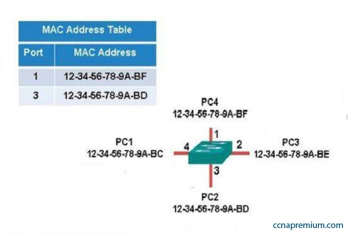
The following exhibit displays the MAC address table of a switch in your network, along with the location of each device connected to the switch:
Which of the following frames will be flooded to all ports after it is received by the switch?
A. source MAC: 12-34-56-78-9A-BD, destination MAC: 12-34-56-78-9A-BF
B. source MAC: 12-34-56-78-9A-BF, destination MAC: 12-34-56-78-9A-BD
C. source MAC: 12-34-56-78-9A-BF, destination MAC: 12-34-56-78-9A-BC
D. source MAC: 12-34-56-78-9A-BC, destination MAC: 12-34-56-78-9A-BF
Correct Answers: C
Explanation:
The frame with a source MAC of 12-34-56-78-9A-BF and a destination MAC of 12-34-56-78-9A-BC would be sent to all ports because the destination MAC address is not already in the MAC address table.
The frame with a source MAC of 12-34-56-78-9A-BD and a destination MAC of 12-34-56-78-9A-BF would not be sent to all ports because the destination MAC address is in the MAC address table.
The frame with a source MAC of 12-34-56-78-9A-BF and a destination MAC of 12-34-56-78-9A-BD would not be sent to all ports because the destination MAC address is in the MAC address table.
The frame with a source MAC of 12-34-56-78-9A-BC and a destination MAC of 12-34-56-78-9A-BF would not be sent to all ports because the destination MAC address is in the MAC address table.
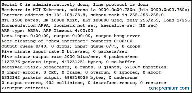
Refer to the partial output of the show interfaces command:
What does the Serial 0 is administratively down, line protocol is down line indicate with certainty?
A. There is no problem with the physical connectivity.
B. There is a configuration problem in the local or remote router.
C. There is a problem at the telephone company’s end.
D. The shutdown interface command is present in the router configuration.
Correct Answers: D
Explanation:
The Serial 0 is administratively down, line protocol is down line in the output of the show interfaces command indicates the following:
The shutdown interface command is present in the router configuration. This indicates that the administrator might have manually shut down the interface by issuing the shutdown command.
A duplicate Internet Protocol (IP) address might be in use.
This line does not show that there is no problem with the physical connectivity. Since the interface is administratively shut down, there is no way of determining the operational status of the physical layer.
The Serial 0 is administratively down, line protocol is down line does not indicate a configuration problem in the local or remote router. A problem in the configuration of local or remote router would be indicated by the Serial 0 is up, line protocol is down message.
This line does not show that there is a problem at the telephone company’s end. Since the interface is administratively shut down, there is no way of determining the operational status of the physical layer or protocol layer on the other end of the line.
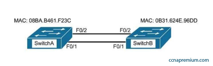
Which switch port(s) will be in a forwarding state? (Choose two.)
A. SwitchA – Fa0/1 and Fa0/2
B. SwitchA – Fa0/1
C. SwitchA – Fa0/2
D. SwitchB – Fa0/1
E. SwitchB – Fa0/2
Correct Answers: A, D
Explanation:
Both switch ports on Switch A and Fa0/1 on Switch B will be in a forwarding state. Switch A will become the STP root bridge due to its lower MAC address. All ports on the root bridge will become designated ports in a forwarding state. Switch B has redundant connectivity to the root bridge, and must block one of its interfaces to prevent a switching loop. Both interfaces are the same speed (FastEthernet), and thus their cost to the root is the same. Finally, the interface with the lowest number will become the forwarding port. F0/1 has a lower port number than F0/2, so F0/1 becomes a forwarding port, and F0/2 becomes a blocking port.
In this scenario there are only two switches in the diagram. However, if there were more switches and Switch A were not the root bridge, the result would be the same with regard to the ports between Swicth A and B. Whenever there are redundant links between switches, one of the four ports involved will be set to a blocking (or in the case of RSTP, discarding) mode. The logic will still be the same, since the cost to get to the root bridge will still be equal if the port speeds are equal.
Without STP (which can be disabled) operating on switches with redundant links, such as those in the figure, loops can and almost surely will occur. For example, if a host connected to SwitchA were to send an ARP request for the MAC address of a host connected to SwitchB, the request could loop and cause a broadcast storm, slowing performance dramatically. This would probably occur when any host connected to either switch sends a broadcast frame, such as a DHCP request.
Rapid Spanning Tree Protocol (RSTP) uses the term discarding for a switch port that is not forwarding frames.
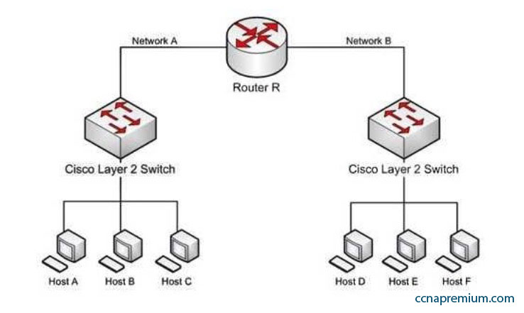
Refer to the network diagram in the exhibit. Host A is configured with an incorrect default gateway. All other computers and the Router are known to be configured correctly.
Which of the following statements is TRUE?
A. Host C on Network A cannot communicate with Host A on Network A.
B. Host A on Network A can communicate with all other hosts on Network A.
C. Host A on Network A can communicate with Router R.
D. Host C on Network A cannot communicate with Router R.
E. Host D on Network B cannot communicate with Host B on Network A.
Correct Answers: B, C
Explanation:
Host A on Network A can communicate with all other hosts on Network A and with Router R. To communicate with local hosts and the interface of Router R (which are all in the same subnet) only a correct IP address is reqired. If the default gateway of Host A is incorrect, then it will not be able to communicate with any host on the other side of the router, which includes Network B in the diagram. Packets from hosts on Network B will reach Host A on Network A without any problem, because they possess the correct address of the default gateway or router, but Host A will send the packet to a dead end because Host A has an incorrect default gateway. On the other hand, Host A does not require a default gateway to communicate with other hosts on same network.
Host C on Network A WILL be able to communicate with Host A on Network A , even though Host A has an incorrect default gateway because Host A and C are in the same subnet, which requires no use of the of the gateway or router..
Host C on Network A WILL be able to communicate with Router R because Host C has the correct default gateway address which is the address of Router R. Host D on Network B WILL be able to communicate with Host B on Network A because both hosts have a correct default gateway address.
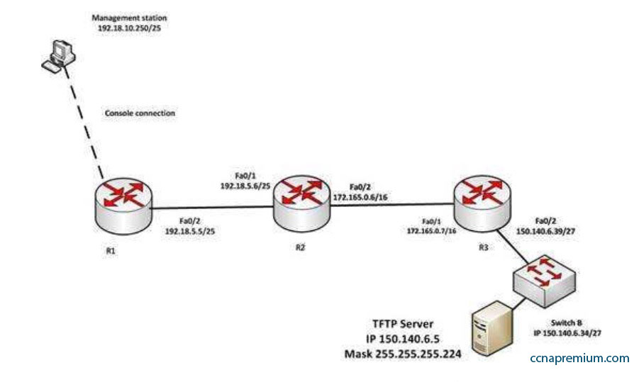
You have established a console session with R1 and you are attempting to download an IOS image from the TFTP server in the diagram below.
However, you are unable to make the connection to 150.140.6.5. What is the problem?
A. The IP address of the management station is incorrect
B. The interfaces between R1and R2 are not in the same subnet
C. The IP address of Switch B is incorrect
D. The IP address of the TFTP server is incorrect
Correct Answers: D
Explanation:
The IP address of the TFTP server is incorrect. The TFTP server, Switch B and the Fa0/2 interface on R3 should all be in the same subnet. With a 27-bit mask (255.255.255.224) against the 150.140.0.0 classful network the resulting subnets are:
150.140.0.0
150.140.0.32
150.140.0.64
and so on, incrementing in intervals of 32 in the last octet until it reaches the 150.140.6.0 subnet. 150.140.6.0
150.140.6.32
150.140.6.64
At this point, we can see that Switch B and the router interface are in the 150.140.6.32 subnet, while the TFTP server is in the 150.140.6.0 subnet. The IP address of the TFTP server needs to be in the 150.140.6.33-150.140.6.62 range, while avoiding the addresses already used on R1 and the switch.
The IP address of the management station does not appear to be in any of the networks listed in the diagram, but that doesn’t matter since the connection to the router is through the console cable which does not require a correct IP address.
The Fa0/2 and Fa0/1 interfaces on R1 and R2 are in the same subnet. Using a 25-bit mask against the 192.18.5.0/24 classful network yields the following subnets:
192.18.5.0
192.168.5.128
Both router interfaces in question are in the 192.18.5.0 subnet.
As we have already determined, the IP address of Switch B is correct. Even if it were incorrect or missing altogether, it would have no impact on connecting to the TFTP server. Switches merely switch frames based on MAC addresses and only need an IP address for management purposes.
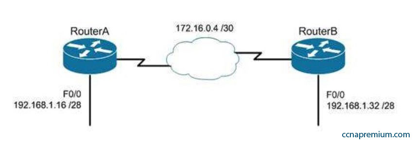
Which of the following routing protocols could NOT be used with this design?
A. RIPv1
B. RIPv2
C. EIGRP
D. OSPF
Correct Answers: A
Explanation:
The network design displayed has subnets of a major classful network located in opposite directions from the perspective of some of the individual routers. This configuration can be accommodated by any routing protocol that supports Variable Length Subnet masks (VLSM) or the transfer of subnet mask information in routing advertisements.
RIPv1 supports neither of these. RIPv1 will automatically summarize routing advertisements to their classful network (in this case 192.168.1.0/24). This action will cause some of the routers to have routes to the same network with different next hop addresses, which will NOT work.
EIGRP, RIPv2 and OSPF all support VLSM and can be used in the design
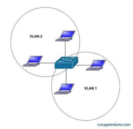
Which of the following statements are true with regard to the network shown in the exhibit?
A. there is one broadcast domain and one collision domain
B. there is one broadcast domain and four collision domains
C. there are two broadcast domains and two collision domains
D. there are two broadcast domains and four collision domains
E. the hosts in VLAN1 could use IP addresses 192.168.5.4/24 and 192.168.5.5/24 and the hosts in VLAN2 could use IP addresses 192.168.6.1/24 and 192.168.6.2/24
F. the hosts in VLAN2 could use IP addresses 192.168.5.5/24 and 192.168.6.5/24
Correct Answers: D, E
Explanation:
There are two broadcast domains and four collision domains in the network shown in exhibit. A Virtual LAN (VLAN) is a group of networking devices in the same broadcast domain. A broadcast domain is a group of devices such that when one device in the group sends a broadcast, all the other devices in the group will receive that broadcast. Because there are two VLANs shown in the exhibit, VLAN1 and VLAN2, there are two broadcast domains. A switch will not forward broadcast frames between VLANs.
A collision domain is a domain where two or more devices in the domain could cause a collision by sending frames at the same time. Each switch port is a separate collision domain. Because there are four switch ports in the exhibit, there are four collision domains.
The hosts in VLAN1 could use IP addresses 192.168.5.4/24 and 192.168.5.5/24 and the hosts in VLAN2 could use IP addresses 192.168.6.1/24 and 192.168.6.2/24. Hosts in different VLANs must have IP addresses that are in different subnets.
The other options that offer IP address plans are incorrect because they either place hosts from different VLANs in the same subnet, or place hosts in the same VLAN in different subnets.
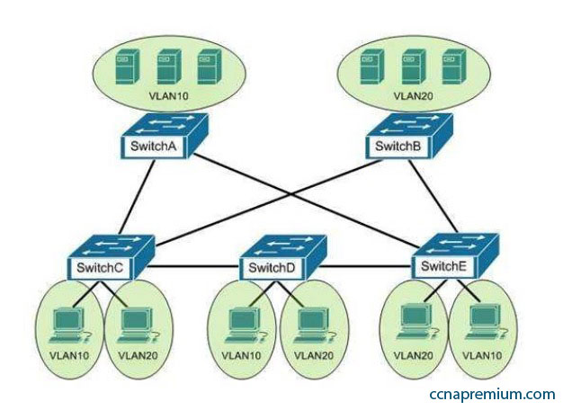
You are the switch administrator for InterConn. The network is physically wired as shown in the diagram. You are planning the configuration of STP. The majority of network traffic runs between the hosts and servers within each VLAN.
You would like to designate the root bridges for VLANS 10 and 20. Which switches should you designate as the root bridges?
A. Switch A for VLAN 10 and Switch E for VLAN 20
B. Switch A for VLAN 10 and Switch C for VLAN 20
C. Switch A for VLAN 10 and Switch B for VLAN 20
D. Switch D for VLAN 10 and Switch B for VLAN 20
E. Switch E for VLAN 10 and Switch A for VLAN 20
F. Switch B for VLAN 10 and Switch E for VLAN 20
Correct Answers: C
Explanation:
You should designate Switch A for VLAN 10 and Switch B for VLAN 20. The STP root bridge for a particular VLAN should be placed as close as possible to the center of the VLAN. If the majority of network traffic is between the hosts and servers within each VLAN, and the servers are grouped into a server farm, then the switch that all hosts will be sending their data to is the ideal choice for the STP root. Cisco’s default implementation of STP is called Per-VLAN Spanning Tree (or PVST), which allows individual tuning of the spanning tree within each VLAN. Switch A can be configured as the root bridge for VLAN 10, and Switch B can be configured as the root bridge for VLAN 20, resulting in optimized traffic flow for both.
None of the other switches is in the traffic flow of all data headed towards the VLAN 20 or VLAN 10 server farms, so they would not be good choices for the root bridge for either VLAN. Care should be taken when adding any switch to the network. The addition of an older, slower switch could cause inefficient data paths if the old switch should become the root bridge.
In the network exhibit, the routers are running OSPF and are set to the default configurations.
What would be the effect of configuring a loopback interface on Router A with an address of 192.168.1.50/24?
A. Router B would become the DR
B. Router A would become the DR
C. Router C would become the DR
D. Router A would become the BDR
Correct Answers: B
Explanation:
Configuring a loopback interface on RouterA with an address of 192.168.1.50/24 would cause Router A to become the designated router (DR). The designated router (DR) is determined by the router with the highest interface priority number. If the priority numbers are tied, then the router with the highest router ID (RID) becomes the DR.
The default priority number is 1, and can be configured as high as 255. Changing the priority to 0 would make the router ineligible to become the DR or the backup designated router (BDR). The ip ospf priority # command is used to manually configure a priority on a specific interface.
Router IDs are determined first by the highest loopback IP address, followed by the highest IP address on an active physical interface. Thus, in the case of a priority tie, the router with the highest loopback IP address will have the highest RID, and will become the DR for the network segment.
The current Router ID for a router can be determined by executing the show ip interface brief command. In the sample output of the show ip interface brief command below, the RID will be 10.108.200.5.
Router# show ip interface brief
Interface IP-Address OK? Method Status Protocol Ethernet0 10.108.00.5 YES NVRAM up up
Ethernet1 unassigned YES unset administratively down down Loopback0 10.108.200.5 YES NVRAM up up
Serial0 10.108.100.5 YES NVRAM up up Serial1 10.108.40.5 YES NVRAM up up Serial2 10.108.100.5 YES manual up up
Serial3 unassigned YES unset administratively down down
Neither Router B nor C will be the DR because the IP addresses on their physical interfaces are lower than 192.168.1.50/24. Router A will not be the backup designated router. Since it is the DR, it cannot also be the BDR.
Router C will not be the BDR because its IP address is lower than that of Router B. Router B will be the BDR.
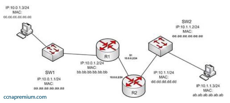
In the diagram below, if the workstation at 10.0.1.3 sends a packet to the workstation at 10.1.1.3, what will be the source physical address when the packet arrives at 10.1.1.3?
A. ab.ab.ab.ab.ab.ab
B. ee.ee.ee.ee.ee.ee
C. dd.dd.dd.dd.dd.dd
D. cc.cc.cc.cc.cc.cc
E. aa.aa.aa.aa.aa.aa
F. bb.bb.bb.bb.bb.bb
Correct Answers: C
Explanation:
The source physical address of the packet when it arrives at 10.1.1.3 will be that of the interface on the R2 router, dd.dd.dd.dd.dd.dd . Each router will change the MAC address field to the MAC address of its sending interface as it sends the packet and will leave the IP address field unchanged. The switches will change neither field, but will simply use the MAC address field to determine the forwarding path and switch the frame to the port where the MAC address is located. The R2 router is the last device that will make a change to the MAC address field.
The source (10.0.1.3) and destination (10.1.1.3) IP address fields will stay the same at each device. The MAC address field changes when R1 sends the frame to R2 and when R2 send the frame to the workstation at 10.1.1.3.