A user is unable to connect to the Internet. Based on the layered approach to troubleshooting and beginning with the lowest layer, drag each procedure on the left to its proper category on the right.
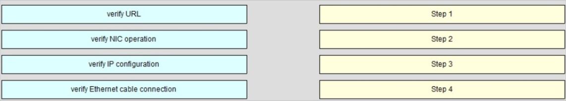
Select and Place:
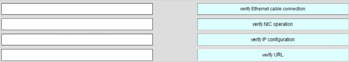
A user is unable to connect to the Internet. Based on the layered approach to troubleshooting and beginning with the lowest layer, drag each procedure on the left to its proper category on the right.
Select and Place:
Refer to the exhibit.
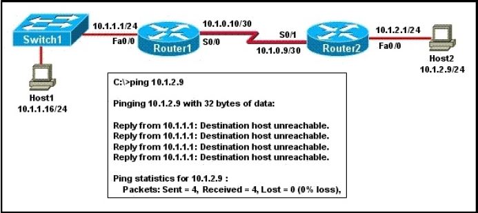
A network administrator attempts to ping Host2 from Host1 and receives the results that are shown. What is the problem?
A. The link between Host1 and Switch1 is down.
B. TCP/IP is not functioning on Host1
C. The link between Router1 and Router2 is down.
D. The default gateway on Host1 is incorrect.
E. Interface Fa0/0 on Router1 is shutdown.
F. The link between Switch1 and Router1 is down.
Refer to the exhibit.
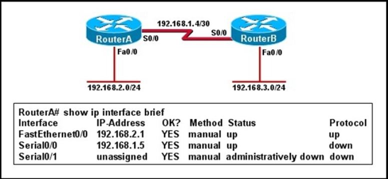
Hosts in network 192.168.2.0 are unable to reach hosts in network 192.168.3.0. Based on the output from RouterA, what are two possible reasons for the failure? (Choose two.)
A. The cable that is connected to S0/0 on RouterA is faulty.
B. Interface S0/0 on RouterB is administratively down.
C. Interface S0/0 on RouterA is configured with an incorrect subnet mask.
D. The IP address that is configured on S0/0 of RouterB is not in the correct subnet.
E. Interface S0/0 on RouterA is not receiving a clock signal from the CSU/DSU.
F. The encapsulation that is configured on S0/0 of RouterB does not match the encapsulation that is configured on S0/0 of RouterA.
Refer to the exhibit.
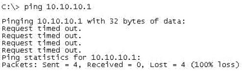
An administrator pings the default gateway at 10.10.10.1 and sees the output as shown. At which OSI layer is the problem?
A. data link layer
B. application layer
C. access layer
D. session layer
E. network layer
Refer to the exhibit.
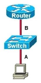
The two connected ports on the switch are not turning orange or green. What would be the most effective steps to troubleshoot this physical layer problem? (Choose three.)
A. Ensure that the Ethernet encapsulations match on the interconnected router and switch ports.
B. Ensure that cables A and B are straight-through cables.
C. Ensure cable A is plugged into a trunk port.
D. Ensure the switch has power.
E. Reboot all of the devices.
F. Reseat all cables.
Refer to the exhibit.
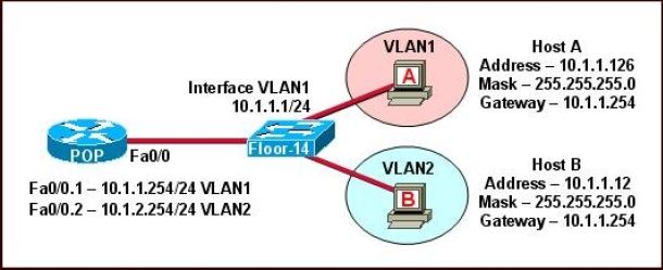
The network shown in the diagram is experiencing connectivity problems. Which of the following will correct the problems? (Choose two.)
A. Configure the gateway on Host A as 10.1.1.1.
B. Configure the gateway on Host B as 10.1.2.254.
C. Configure the IP address of Host A as 10.1.2.2.
D. Configure the IP address of Host B as 10.1.2.2.
E. Configure the masks on both hosts to be 255.255.255.224.
F. Configure the masks on both hosts to be 255.255.255.240.
Refer to the exhibit.
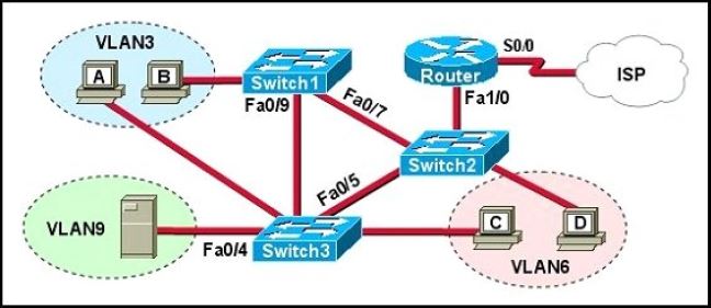
A problem with network connectivity has been observed. It is suspected that the cable connected to switch port Fa0/9 on Switch1 is disconnected. What would be an effect of this cable being disconnected?
A. Host B would not be able to access the server in VLAN9 until the cable is reconnected.
B. Communication between VLAN3 and the other VLANs would be disabled.
C. The transfer of files from Host B to the server in VLAN9 would be significantly slower.
D. For less than a minute, Host B would not be able to access the server in VLAN9. Then normal network function would resume.
Refer to the exhibit.
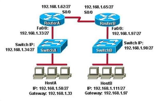
HostA cannot ping HostB. Assuming routing is properly configured, what is the cause of this problem?
A. HostA is not on the same subnet as its default gateway.
B. The address of SwitchA is a subnet address.
C. The Fa0/0 interface on RouterA is on a subnet that can’t be used.
D. The serial interfaces of the routers are not on the same subnet.
E. The Fa0/0 interface on RouterB is using a broadcast address.
Which router IOS commands can be used to troubleshoot LAN connectivity problems? (Choose three.)
A. ping
B. tracert
C. ipconfig
D. show ip route
E. winipcfg
F. show interfaces
A network administrator is troubleshooting the OSPF configuration of routers R1 and R2. The routers cannot establish an adjacency relationship on their common Ethernet link.

The graphic shows the output of the show ip ospf interface e0 command for routers R1 and R2. Based on the information in the graphic, what is the cause of this problem?
A. The OSPF area is not configured properly.
B. The priority on R1 should be set higher.
C. The cost on R1 should be set higher.
D. The hello and dead timers are not configured properly.
E. A backup designated router needs to be added to the network.
F. The OSPF process ID numbers must match.